Posts

1971 Pantera

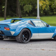
Here’s another great example of a customer’s car wired with our Infinitybox system.  This is a highly customized 1971 DeTomaso Pantera built by Dave A, the cars owner.  The finished product is beautiful.  The stance is aggressive, the color pops and there are custom details all over the car.  All of the pictures in this post were shot by Jason Peacott of Jason Peacott Photography.  You can click here to get to Jason’s website to see his other work.

Low Front View of 1971 Pantera Wired with the Infinitybox System

Low Front View of 1971 Pantera Wired with the Infinitybox System

Dave started with a rusted-out, narrow body Pantera.  All the rot was repaired and then the car was treated to a Group 4 race prep, including seam welding and doublers.  A fully integrated cage was then added, which is stitch welded to the chassis.  The all-steel exterior is a stylized Group 4 tribute.  It was completely shaved and the engine bay & underbody feature all custom metal work.

Front 3/4 View of 1971 Pantera Wired with the Infinitybox System

Front 3/4 View of 1971 Pantera Wired with the Infinitybox System

Dave’s running a race-built LS7 engine, mated to a built G96.50 transmission, breathing through a custom Harrop ITB intake system and 8-into-1 exhaust.  The exhaust work alone is worth the price of admission.

Amazing Exhaust Work on 1971 Pantera

Amazing Exhaust Work on 1971 Pantera

The car features a completely custom interior with special lighting and many one-off parts.

Interior of 1971 Pantera Wired with the Infinitybox System

Interior of 1971 Pantera Wired with the Infinitybox System

Dave wired the car with our 20-Circuit Kit and inLINK.  The wiring is super clean and practically invisible.  The distributed design of our Infinitybox system let Dave put the MASTERCELL and POWERCELLs where he needed them to keep the wiring simple and clean.

Dave has hidden switches on the outside of the car to control his door poppers.  We custom programmed his poppers so they work from his inLINK fobs.  We also programmed the system so that the poppers are disabled when he locks the system from his key fob.  This is a simple but powerful security feature that you can get with your Infinitybox system.

This car was proudly built by Dave with help with a few specialty shops for some of the details.  This includes White Post Restorations who did paint and final assembly.

If you want to learn more about how our Infinitybox system can help you wire your next project, click on this link to connect to our technical support team.

Rear View of 1971 Pantera Wired with the Infinitybox System

Rear View of 1971 Pantera Wired with the Infinitybox System


1967 Camaro at SEMA Battle of the Builders

Jeremy, Tim and the entire team at Miranda Built did it again.  Their 1967 Camaro placed Top 10 in the Hot Rod category and Top 40 overall at the SEMA 2021 Battle of the Builders.  This is another beautiful example of their creativity, skill and attention to detail.  Our Infinitybox team is proud to be a part of this build.

1967 Camaro by Miranda Built Front

1967 Camaro by Miranda Built. Wired with the Infinitybox System.

The Camaro is powered by a supercharged LS3 into a TR6060 6-speed transmission.  It sits on a Roadster Shop chassis with a Ford 9″ rear end.  The attention to detail in this build is exceptional.

1967 Camaro by Miranda Built Engine Bay

1967 Camaro with supercharged LS3 by Miranda Built. Wired with the Infinitybox System.

They wired the car with our 20-Circuit Kit, inMOTION, inLINK and inRESERVE.  We always to a little custom code for the Miranda Built cars to add a few modern electrical touches.  Because of the distributed nature of the Infinitybox system, they can mount our MASTERCELL, POWERCELLs and inMOTION cells where they need them.  All of their wire runs are short and neat.  You can’t see any evidence of the wiring in this car.

1967 Camaro by Miranda Built Dash & Interior

1967 Camaro by Miranda Built. Wired with the Infinitybox System.

This video shows Jeremy Miranda walking through the details of this amazing car.  You can also get more details on the car from their website by clicking here.

We congratulation the Miranda Built team on this awesome win.  Great job guys!

If you want to learn more about how you can wire your car or truck with our Infinitybox system, click this link to talk to our team.


Wiring Tilt Sensor

This blog post will give you the details to wiring a tilt sensor to your Infinitybox system.  Our system has very powerful security and immobilizer functions.  When you add inLINK to your 20-Circuit Kit, you get piece of mind built into your car’s electrical system.  We’ve blogged about the power of our security system previously.  You can read that at this link.  For an added level of security, you can wire a tilt sensor to your system.  This will trigger an alarm if someone tries to tow your car when you have inLINK security enabled.

You can set any MASTERCELL input to be an alarm trigger.  Most commonly, customers elect to use the inputs for the door pin switches to also act as alarm triggers.  Your horn will honk if someone opens a door when you have security enabled from the inLINK key fob.  You can also use any MASTERCELL input and wire that to a tilt-sensor.  Most tilt-sensors close their contacts when the angle of the vehicle exceeds a set threshold.  This would trigger when someone tries to tow the car or if they shake it.  The most popular tilt sensor that we’ve seen is the DEI 507M sensor.

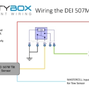
This sensor is smart.  When you turn off the ignition, if learns the angle of the car.  If you parked on a hill, it knows how much the car can move before it will trigger the alarm.  To make this work correctly, you need to add a relay to the 507M module that grounds a signal wire when the ignition is turned off.  This diagram will show you the details.

Picture of Infinitybox wiring diagram showing how to wire a DEI tilt sensor into the Infinitybox system.

Picture of Infinitybox wiring diagram showing how to wire a DEI tilt sensor into the Infinitybox system.

Once you have the relay installed, you will need to wire the blue wire in the 507M harness to the MASTERCELL input that you’ve chosen to be your alarm trigger.  You’ll need to work with our application engineering team to get this set up for your system.

Click here to download a PDF version of this wiring diagram.  

Click this link to contact our team with any questions about wiring a tilt sensor to your Infinitybox system.

inLINK Radio Board Install

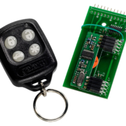
Our inLINK Wireless Control Module is the most popular accessory that guys add to their Infinitybox 20-Circuit Kit.  With inLINK, you can control the functions of your Infinitybox system through a simple key fob.  inLINK seamlessly integrates into your MASTERCELL with no external boxes of modules.  You can enable and disable security.  You can control your lights.  You can pop your doors.  You get a ton of flexibility.

If you buy inLINK with your 20-Circuit Kit, we pre-install it for you at the factory.  If you don’t buy inLINK up front, you can add it at any time.  Installing it to your MASTERCELL is very simple.  You only need a screw driver.  No software updates are needed.  The MASTERCELL is pre-programmed to talk to the inLINK radio receiver board.

The inLINK kit includes the inLINK Radio Receiver Board, two spacers, two screws and two of the inLINK key fobs.  The following instructions show you how to install the inLINK Radio Receiver Board into the MASTERCELL.

STEP 1- Disconnect the MASTERCELL.
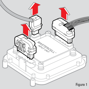
inLINK Installation- Figure 01

inLINK Installation- Figure 01

Unplug the MASTERCELL input harnesses and the CAN cable as shown in Figure 1.  Remove the MASTERCELL from the car.

STEP 2- Remove the Screws from the Back of the MASTERCELL.
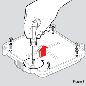
inLINK Installation- Figure 02

inLINK Installation- Figure 02

Turn over the MASTERCELL so the inSIGHT screen is facing down as shown in Figure 2.  Remove all 8 screws from the back of the MASTERCELL with a Phillips screwdriver.  Put these screws in a safe place.

STEP 3- Remove the Back of the MASTERCELL
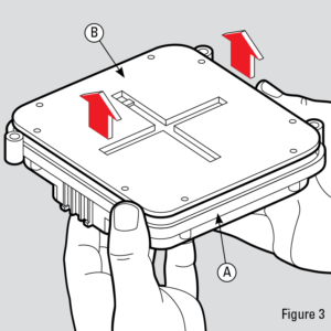
inLINK Installation- Figure 03

inLINK Installation- Figure 03

Once the screws are removed, carefully separate the plastic housing (A) from the back cover (B) as shown in Figure 3.  Carefully separate the housing and back cover of the MASTERCELL unit by first turning the unit upside down and gently placing your fingers in the input connector shells.  Gently press up on the connector pins while holding the plastic housing (A) with your thumbs until the back cover is separated from the housing.  Be sure to keep the plastic housing facing down to keep the buttons in place. If they do fall out, locate all five buttons and put them to the side.  Set aside the plastic housing, keeping it upside-down so that the buttons do not fall out.

STEP 4- Prepare the inLINK Radio Receiver Board.
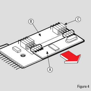
inLINK Installation- Figure 04

inLINK Installation- Figure 04

Disconnect the daughter board (A) in Figure 4 from the sockets (C) on the radio receiver board (B).  Be careful not to bend the pins when removing.

STEP 5- Place the Spacers on the MASTERCELL Board.
inLINK Installation- Figure 05

inLINK Installation- Figure 05

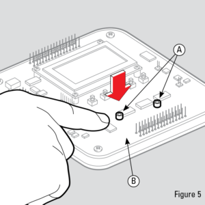
Place the two clear spacers (A) on the board (B) as shown in Figure 5.  The two spacers should go over the holes in the MASTERCELL printed circuit board.

STEP 6- Install the inLINK Radio Receiver Board.
inLINK Installation- Figure 06

inLINK Installation- Figure 06

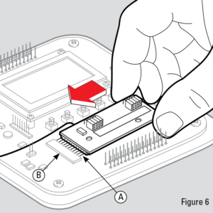
While keeping the spacers in place, carefully align the pins on the radio receiver board (A) with the header on the MASTERCELL board (B) as shown in Figure 6.  Insert the radio board pins (A) into the MASTERCELL connecting header (B) and push in the board until the plastic connector on the radio receiver board meets with the header on the MASTERCELL board.  Ensure that the spacers are still aligned with the holes prior to securing the radio receiver board with screws. If the spacers are not aligned, CAREFULLY put them back in place using a small tool.

STEP 7- Install inLINK Board Screws.
inLINK Installation- Figure 07

inLINK Installation- Figure 07

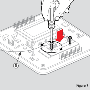
Fasten the radio receiver board to the MASTERCELL board by inserting the included screws into the holes as shown in Figure 7 and tighten the screws until the board is secure.  DO NOT OVER-TIGHTEN THESE SCREWS.

STEP 8- Reinstall the inLINK Daughter Board.
inLINK Installation- Figure 08

inLINK Installation- Figure 08

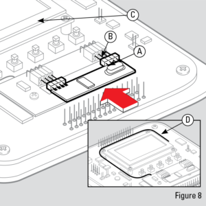
Align daughter board (A) pins with the top row of holes on the radio board header (B) as shown in Figure 8 and insert pins. Push in the daughter board until both headers are flush.  Wrap antenna wire (D) in Figure 7 and Figure 8 in a large circle around the inSIGHT diagnostic module (C) in figure 8. Make sure that it does not interfere with the pins or plastic mating surfaces.

STEP 9- Replace the MASTERCELL Buttons
inLINK Installation- Figure 09

inLINK Installation- Figure 09

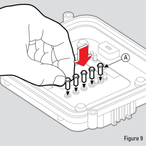
If any of the MASTERCELL buttons fell out of the housing, reinstall them as shown in Figure 9.

STEP 10- Reassemble MASTERCELL.
inLINK Installation- Figure 10

inLINK Installation- Figure 10

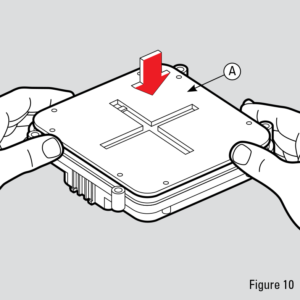
Keeping the housing upside-down, insert the MASTERCELL board and back cover (A) as shown in Figure 10 by aligning the input pins with the correct holes in the housing. DO NOT flip over the front cover as this will cause the buttons to fall out. Gently press the cover down until all pins have gone through their corresponding openings
on the housing and the back cover fits snugly in place.

STEP 11- Reinstall Screws on Back Cover of MASTERCELL.
inLINK Installation- Figure 11

inLINK Installation- Figure 11

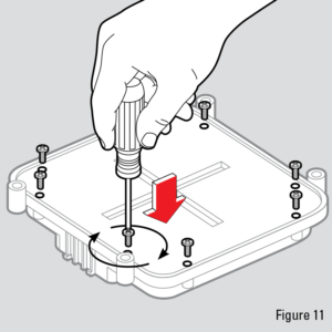
Insert screws back into the holes on the back cover and tighten until the cover is securely fastened.  DO NOT OVER-TIGHTEN THESE SCREWS.

STEP 12- Reinstall MASTERCELL In Car.
inLINK Installation- Figure 12

inLINK Installation- Figure 12

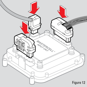
Mount MASTERCELL input unit back into your vehicle and plug all connectors back into their proper location as shown left in Figure 12.

Power up your Infinitybox system once you have completed these steps.  You will need to train your inLINK key fobs to the MASTERCELL after the Radio Receiver Board has been installed.  Click on this link to get to the instructions to train your inLINK Key Fobs.

Contact our technical support team if you have any questions on how to install your inLINK module in your Infinitybox 10 or 20-Circuit Kit.

inLINK Video

Our inLINK Wireless Control Accessory is our most popular add-on to our 20-Circuit Kit.  It gets you powerful control of your car’s electrical features through a simple 4-button key fob.  The inLINK accessory comes with a small radio receiver that gets installed inside your MASTERCELL.  There is no external box that you need to make inLINK work.  We recently published this video that shows you the details of inLINK and what it can do for your car or truck wired with our Infinitybox system.  Check it out here.

You can visit the product page for inLINK at this link. 

You can learn more about the security and immobilizing features of inLINK at this link.  

This link will take you to a video showing inLINK in action.  

Picture of a finished Factory Five GTM wired with the Infinitybox system

Showing off inLINK in a Factory Five GTM

We have been working with a customer to finish the details of a Factory Five GTM build.  This car was wired with our 20-Circuit KitinMOTIONinRESERVEinTOUCH NETinVIRONMENT and inLINK.  Essentially, the car has the works.  It was originally built and wired by Shane Vacek at Vraptor Speed Works.  Izzy Dunn at Dunn Customz just finished the details on the car for the customer.

This video shows a walk around of the finished car.  It turned out great.  You can see the front POWERCELL mounted under the hood.

In this blog post, we want to feature one of the simplest accessories in the Infinitybox lineup.  That is inLINK.  inLINK gets you wireless control of your car or truck from a simple key fob.  You can turn on your lights remotely, pop your doors and trunk, and enable the Infinitybox security system.

Since your Infinitybox system is controlling the ignition, fuel pump and starter, we can easily stop someone from starting the car and driving off with it.   When you press the “lock” button on the inLINK key fob, we disable the ability to turn on the ignition, power the fuel pump and crank the starter.  Even if someone where able to get in the car with inLINK security enabled, the MASTERCELL completely blocks the ability to get the engine running.  The best part is that this is completely integrated into our Infinitybox system.  You do not need to buy a separate security or immobilizer system and integrate it into your wiring harness.

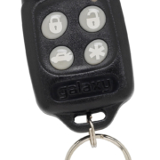
When you’re ready to drive the car, you simply press the “unlock” button on the key fob and you’re ready to go.

The owner of this car wanted door poppers.  They are using POWERCELL outputs to power a solenoid in each door.  They can push a button inside the car to pop these solenoids.  They also have buttons on the outside of the doors that let them pop the doors.  They also wanted to be able to pop the doors from buttons on the key fob.

All of this is very easy with the Infinitybox system.  Our team custom programmed the door popper outputs to pulse for 1 second.  The customer can push buttons on the key fob or use buttons on the door.  Very simple.

Here’s the coolest part of all.  The customer wanted buttons on the outside of the car to be able to pop the doors.  However, the customer does not want those buttons to work when security is enabled.  That is a very simple thing to do with our Infinitybox system.  As part of our custom programming, we set the MASTERCELL inputs to be disabled when security is on.  That way, no one can walk up to the car and open the doors unless they have the inLINK key fobs specifically programmed to that car.  The video below shows how this works.  You can see how security is enabled and disabled.  You can see how the doors can be popped from the inLINK key fobs and you can see how inLINK security disables the exterior switches.

Thanks to Izzy for sharing these pictures and videos.

Click on this link to contact our team to learn more about what our Infinitybox system can do for your build.

Security

We received a great question from a potential customer. He was looking to add the Infinitybox inLINK wireless upgrade to his system and wanted to know how secure it was.

inLINK is a great option for your Infinitybox kit because it easily adds remote control to your wiring system. You get our inLINK radio module and two key fobs. The radio module easily installs in the MASTERCELL.  If you purchase inLINK with your kit, we pre-install it for you. If you purchase it later, it is very easy to install yourself. It is completely plug & play with no software required.  This link will take you to the instructions to install inLINK in your MASTERCELL.

You can use your Infinitybox inLINK key fobs to control many things including your lighting, popping your doors and expressing-down your windows.  Most importantly, inLINK gets you security and alarm functions. When you press the lock button on the inLINK key fob, Infinitybox completely disables the inputs for the ignition, starter and fuel pump. This is done from within the MASTERCELL so it is very secure. If you try to start the car when Infinitybox security is on, you get a clear message on the inSIGHT LCD module alerting you that the car cannot be started. Additionally, you can tie MASTERCELL inputs to switches in your car so that if they are triggered when security is on, you can sound the horn or an external siren. This makes inLINK a very powerful vehicle immobilizer and alarm that is built right into Infinitybox with no additional wiring required.

Since inLINK is the key to the vehicle’s security, the question about the wireless encryption is important. We use Microchip’s KEELOQ hardware and encryption technology for inLINK. This is the exact same technology used in OEM remote entry systems, vehicle alarms, highway toll collection, garage door openers and medical device monitoring.

KEELOQ uses a frequency hopping, 64-bit code system. There are over 4-billion code combinations and every time you press a button, the system randomly generates a new code. The hardware is designed never to react to the same code twice. If you could try each of the different code combinations, it would take you 17-years to go through all of them.

We have our own seed key that is unique to Infinitybox so that other devices using the same KEELOQ technology cannot link to our system.

The Infinitybox inLINK system uses an industry proven, rock-solid technology to ensure reliable transmissions and hack-proof security.

You can learn more about inLINK at this link.

Training inLINK

inLINK is one of our most popular accessories for our 10 and 20-Circuit Harness Kits.  It gets you a very easy way to add an alarm, security and a vehicle immobilizer to your car.  You can either purchase inLINK with your kit up front or you can add at any time down the road.  If you add it down the road, you are going to have to follow these instructions for training inLINK.  This is a simple process that pairs the remote key fob to the radio in the MASTERCELL.

We use a secure and encrypted system to protect the communication between the key fob and the MASTERCELL.  It uses a 64-bit, rolling code encryption scheme.  That means that every time you press a button on the fob, it changes the secret password.  There are billions of combinations of passwords that make hacking into the transmission practically impossible.

Each of the key fobs included with the inLINK kit has to be trained to the MASTERCELL.  If you order inLINK with your 10 or 20-Circuit Harness Kit, we pre-install it and train it for you.  If you order this separately, you need to install the radio board and train the key fobs.

This link will show you how to install the inLINK radio board in your MASTERCELL.

Here are the steps to train your key fobs to your MASTERCELL.

  1. Remove the cover on the MASTERCELL.
  2. Press and release the “TRAIN” button on the MASTERCELL.  You will get a message that will read “To Learn… press any button 2 times”.
  3. Press the lock button on the key fob once, wait one second and press the lock button on the key fob again.  After a few seconds, you will get a message on the screen that reads “Learn Command Accepted”.  You may also get a message that reads “Existing Transmitter Overwritten”.  In either case, the MASTERCELL and key fob are paired.
  4. Repeat this process for the second key fob.

Contact our technical support team with any questions about pairing your inLINK key fobs to the MASTERCELL.