FAST XFI 2.0 Wiring
Electronic Fuel Injection systems have completely changed the way guys control their engines in resto-mods, street rods, kit cars and Pro-Touring builds. All the new systems are simple to install, can control hundreds of horse power and automatically tune themselves. Fuel Air Spark Technology (FAST) has been one of the most significant innovators in the area of EFI systems for the restoration and performance markets. Our Infinitybox plays nicely with any EFI system on the market including the full range from FAST. This blog post will show you how to integrate their FAST XFI 2.0 system with our Infinitybox 20-Circuit Kit.
This blog post is going to walk you through the details of wiring your FAST XFI 2.0 EFI system with our Infinitybox system. Specifically, we’re going to talk about wiring primary power, wiring ignition power, wiring the fuel pump trigger and wiring the cooling fan trigger. All of the rest of the connections between the FAST XFI 2.0 and the engine are covered in their instructions. Please carefully read and thoroughly understand the manual for your EFI system before you go any further. The manual and wiring diagrams for the XFI 2.0 are built into their tuning software package. You can download that by clicking this link.
The following wiring diagram shows all of the connections between the FAST XFI 2.0 and the Infinitybox system.
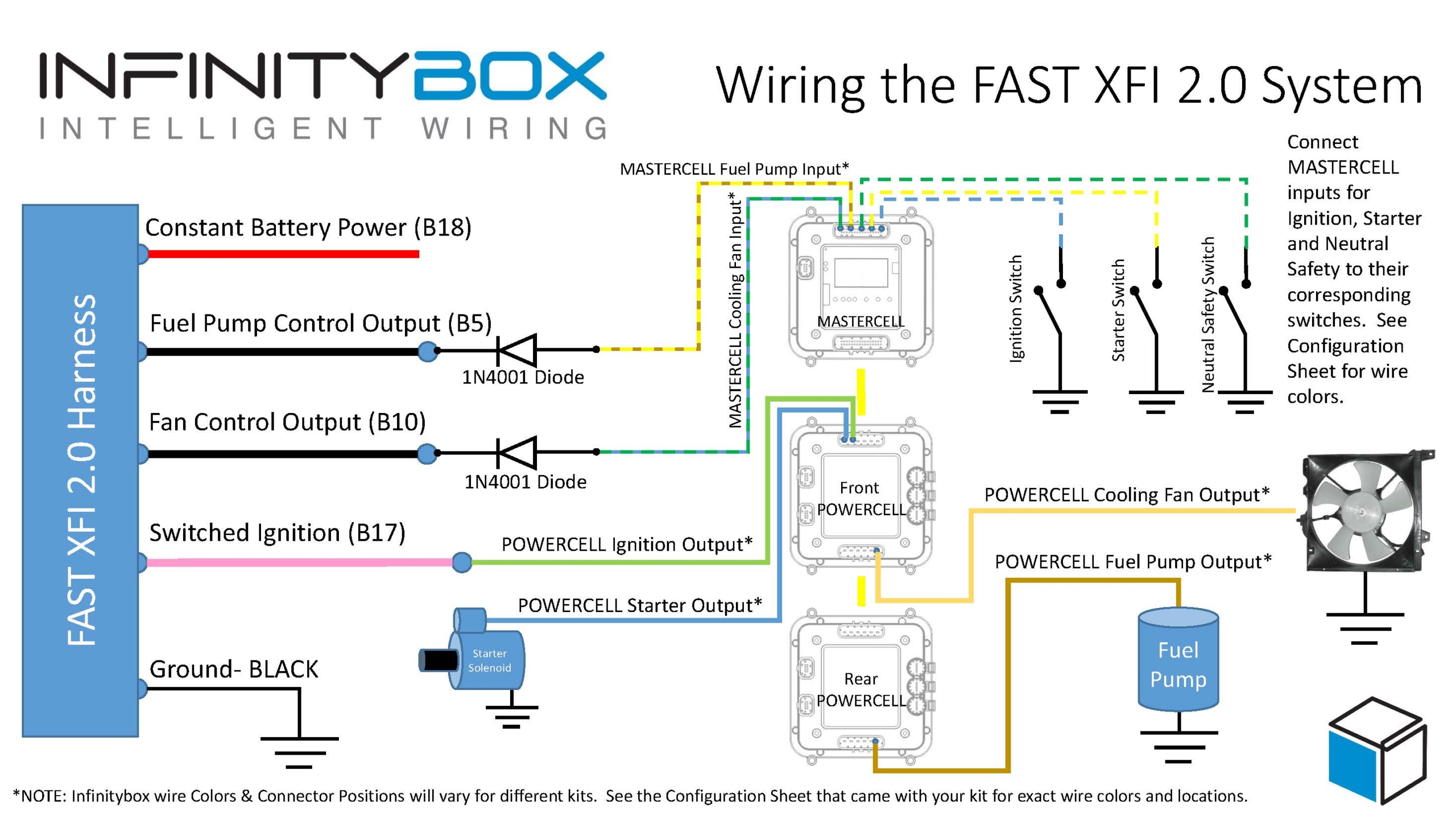
Picture of a wiring diagram showing the connections between the FAST XFI 2.0 and the Infinitybox System.
Just like most other electrical systems in your car, the XFI 2.0 needs constant 12-volt power from the battery. This connection is the red wire going to cavity B18 in their harness. This wire must be connected directly to the positive terminal on your battery. It is also highly recommended that you have a fuse protecting this wire. The FAST manual recommends a 3-amp fuse in-line between the battery and the XFI 2.0 controller.
Next, you need to provide ignition power to the XFI controller. When your key is in the run position, the Infinitybox system will provide switched ignition power to the XFI controller so that it will control your engine. This ignition power will come from the ignition output from one of your POWERCELLs. Please check the configuration sheet that came with your specific kit to validate the POWERCELL output and wire color. Your POWERCELL output for ignition is going to connect to the Switched Ignition wire on the XFI harness. This is the pink wire going into cavity B17. There is no need to add a fuse to protect this wire since the fuse for it is built into the POWERCELL.
The FAST XFI 2.0 system is smart enough to signal for the cooling fan and fuel pump when it senses that it needs them. You can connect these signals to your Infinitybox MASTERCELL so that your POWERCELLs will control your cooling fans and fuel pump directly. Wiring it this way saves you in the amount of wire you need to run and also eliminates the need for extra relays. Our POWERCELLs have the solid-state relays built into them.
The FAST XFI 2.0 is set up to ground trigger relays for the cooling fan and fuel pump. This is ideal because the MASTERCELL inputs work on ground triggers. We still highly recommend installing diodes between the MASTERCELL and the XFI controller to buffer your Infinitybox system from any stray voltage that could be on the cooling fan and fuel pump triggers. We recommend a 1N4001 diode. These can be purchased from Amazon. The orientation of the diode is very important. If they are installed backwards, the triggers will not work. Please see the orientation in the wiring diagram above. The anode side of the diode should be connected to the MASTERCELL input. The cathode should be connected to the trigger wire on the XFI 2.0 controller.
Your MASTERCELL input wire for the cooling fan will connect to the Fan Control Output wire on the FAST harness. This is the black wire at cavity B10. The 1N4001 wire should be installed per our wiring diagram.
Your MASTERCELL input for the fuel pump trigger will connect to the Fuel Pump Control Output on the FAST harness. This is the black wire at cavity B5 on the FAST harness. Just like the cooling fan input, the diode should be wired per our wiring diagram.
Once you have made these connections to the FAST XFI 2.0 system, follow the manual that came with your 20-Circuit Kit to make the rest of the connections to your ignition switch, starter solenoid, cooling fan and fuel pump.
As you can see, our Infinitybox 20-Circuit is a versatile and power wiring harness system. We can easily interface with any electrical component in your car or truck build. You can download a PDF of this wiring diagram by clicking this link.
Click on this link to get in touch with our technical support team to answer any additional questions about wiring your FAST XFI 2.0 electronic fuel injection system.
 Copyright Infinitybox, LLC 2021. All Rights Reserved.