Wiring Door Pin Switches
This blog post is going to cover how to wire your interior and dome lights. In most cases you want these lights to turn on when you open a door to your car. We’ll show you the best way to wire your door pin switches and connect your POWERCELL outputs to your dome lights and interior lights.
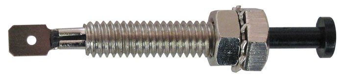
Picture of a door pin switch
Each door in your car has a pin switch. Sometimes these are called door jamb switches. They are very simple devices. They have one terminal on them. This terminal originally connected to the ground side of your dome light circuit. The threaded metal part of the switch connected to your cars ground through the metal part of the door jamb. These switches work backwards from most people would expect. When the car door is open, the contact on the switch is closed to ground. If you think about it, that is what you want. You want the circuit completed when the door is open. In the original wiring on most cars, you had battery power supplied to one side of your dome light. The other side of the light was connected to ground through the door pin switch. When you opened the door, the switch closed. This completed the circuit to ground so the dome light came on.
The inputs to an Infinitybox MASTERCELL work the same way. They get activated when they are connected to ground through a switch. You can learn more about how the MASTERCELL inputs work by clicking this link.
We do not dedicate a POWERCELL output for dome lights or interior lights. You can use any of the OPEN outputs that are listed on your configuration sheet to do this. Simply choose an OPEN output on a POWERCELL and connect that to one side of your dome light circuit. This link will get you more information on using OPEN outputs. Connect the other side of your dome light circuit to ground. Check your configuration sheet and get the MASTERCELL input that corresponds to the OPEN POWERCELL output that you picked. That input is going to connect to your door pin switches.
In most cases, you will want to have your dome lights turn on if any of your car’s doors are opened. This is the same if you have a 2 or 4-door car. To do this, you are going to wire the pin switches in each of your doors in parallel. You are going to take your MASTERCELL input and connect it to each of the terminals on your door pin switches. You can splice off of the input wire at the MASTERCELL and run separate wires to each switch. You can also daisy-chain from one switch to the next in the car. This wiring diagram shows how to connect the MASTERCELL input for your dome lights to the door pin switches.
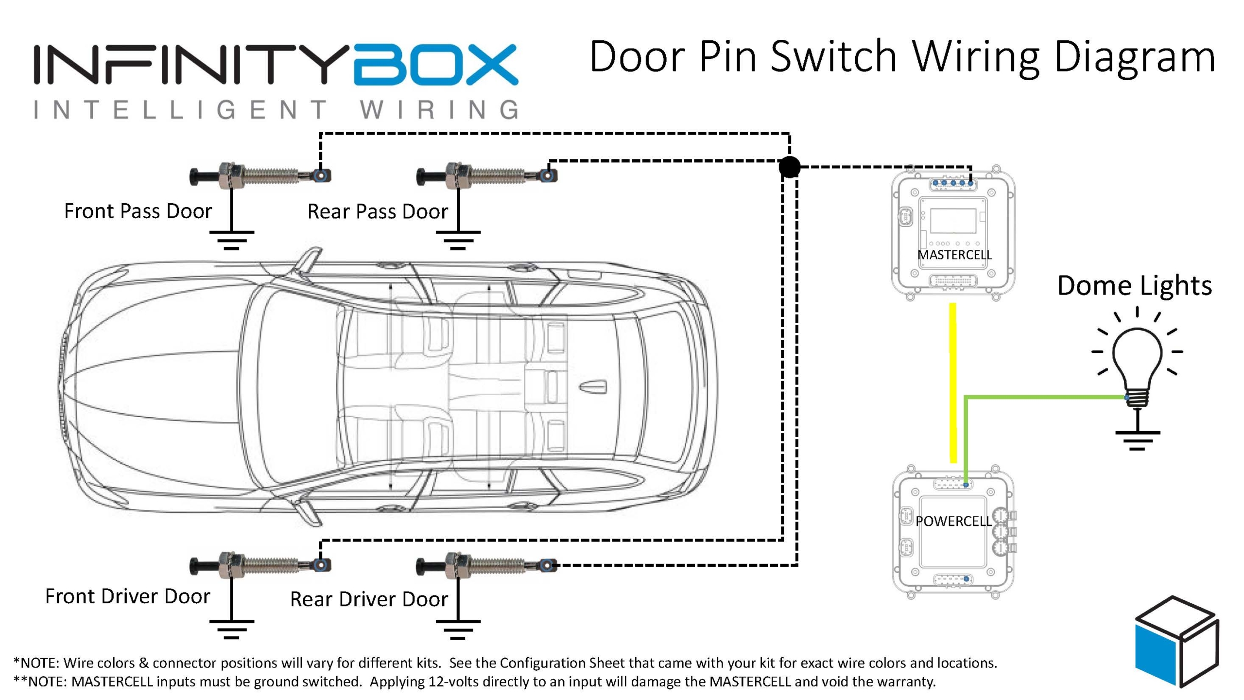
Picture of an Infinitybox wiring diagram showing how to wire door pin switches
If you open one of your doors, the door pin switch will ground the MASTERCELL input. The MASTERCELL will send a command to the POWERCELL to turn on the output for the dome lights. If you open a second door, the input will still be grounded because the switches are wired in parallel. The dome lights will not turn off until you close all of the open doors.
An added bonus of our Infinitybox system is the ability to theater dim your dome lights. When the doors close, we can set your dome light to slowly fade away over 10 seconds. Give our technical support team a call to get this feature on your system.
You can download a PDF copy of this wiring diagram at this link.
If you have questions on how to wire your door pin switches with our Infinitybox system, click on this link to get in touch with our technical support team.