Steering Column
Let’s get to the steering column wiring. This is the next installment the process of wiring our 20-Circuit Kit into a 1967 Mustang. One of our customers sent us a great series of pictures showing their process of wiring their car. It’s time to talk about turn-signal switches, horn switches and 4-way switches.
Our customer is using a steering column kit from IDIDIT. The one they chose is for the 1967 to 1969 Mustang. It is a tilt-style column designed for the shifter on the floor. They choose the option to have the GM steering column connector on the harness. This column also has the Tilt Lever Momentary Switch 510168 option. We are going to use that to control the high-beams and will discuss that in the next blog post. It also has the ignition key built into it. We’ll talk about wiring that in future posts too.
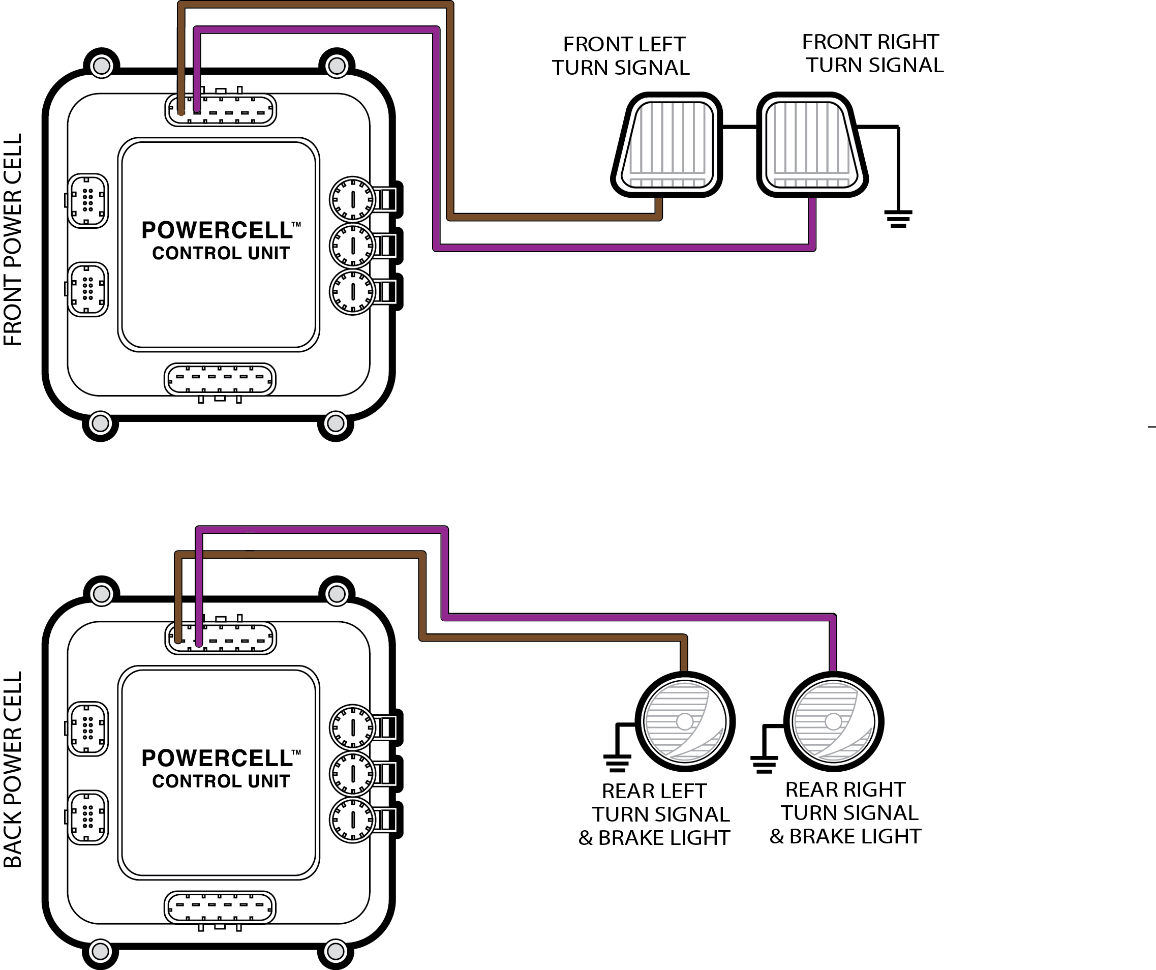
The steering column in the car does a few obvious things. It holds the steering wheel and lets you turn the car. It also holds the switches for the turn-signals, the horn and the 4-way flasher. All of those switches will wire to the inputs on your MASTERCELL. The MASTERCELL will send commands to the different POWERCELLs in the car to turn lights on and off plus sound the horn. Wiring the switches to the MASTERCELL is really easy. There is a diagram on our website that shows how to do this. You can see it here.
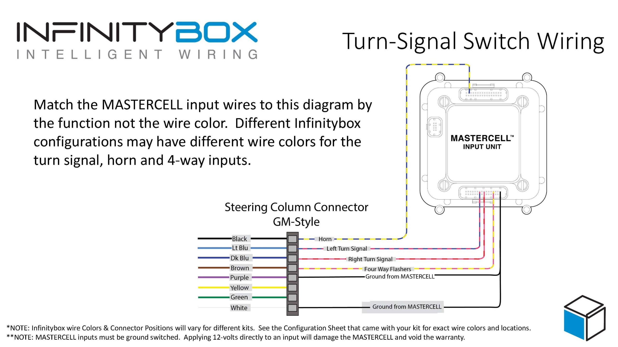
Image of wiring diagram showing how to connect MASTERCELL inputs to a GM-Style Steering Column Connector
Note that most steering column manufacturers use the GM-style turn-signal switch. These have been used in cars for years with very few changes. Companies like IDIDIT and Flaming River use this exact same column switch. The diagram above will work for any of these columns.
The wires colors for the steering column connector are shown on the left side of the wiring diagram above. We also show the details of the connector. Almost all of the wires in the column connector need to connect to MASTERCELL input wires. The two that are unused are the yellow and green wires on the column connector. Check the configuration sheet that came with your kit. You want to match the wire function to the wires on the right of the diagram, not necessarily the wire color. Wire colors may vary from different kits. Always use your configuration sheet for the right wire colors.
The black wire on the column connector needs to connect to your MASTERCELL horn input wire. In our configuration this is the blue wire with the yellow tracer on the A input harness. This is input number 9.
The light blue wire on the column connector needs to connect to your MASTERCELL input for the left turn signal. We’re using the inputs for mechanical steering column. In our configuration this is the yellow wire with the black tracer on the A input harness. This is input 11.
The dark blue wire on the column connector needs to connect to your MASTERCELL input for the right turn signal. We’re using the inputs for mechanical steering column. In our configuration this is the yellow wire with the red tracer on the A input harness. This is input 12.
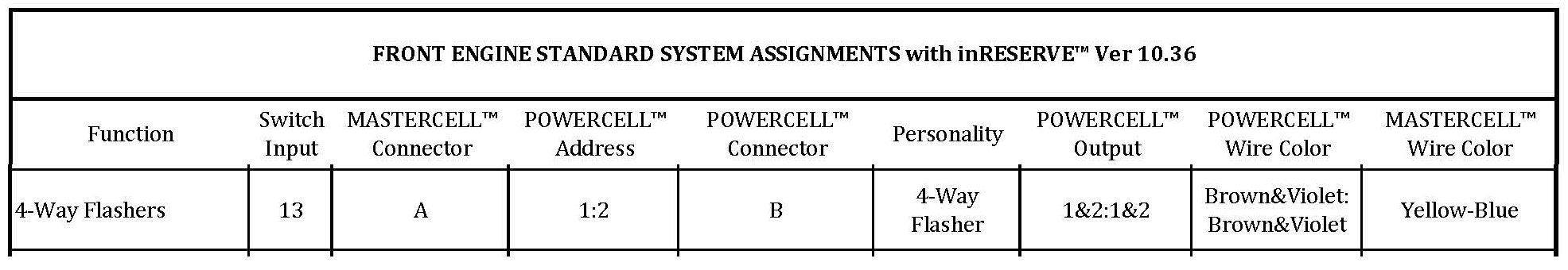
The brown wire on the column connector needs to connect to your MASTERCELL input for the 4-way slashers. In our configuration this is the yellow wire with the blue tracer on the A input harness. This is input 13.
Lastly, the purple and white wires on the column connector needs to be connected to ground. You can use the black wires in the MASTERCELL harness as a ground reference. Otherwise, you can connect these wires to the chassis at the column.
One more comment, you need to properly ground the column to the chassis. Otherwise, you will have problems with your horn switch. In most cases, the column will ground to the frame of the car through its mounts but you will not get a good ground if you have the column shaft painted or powder coated. The same is true if you have a fiberglass body. Run a ground wire from a stationary point on the column to the frame of the car. Make sure that you have a metal-to-metal connection between your ground wire and the points where they connect to the column and the chassis.
You can splice the MASTERCELL input wires directly to the wires on the steering column connector. Alternately, IDIDIT sells a connector kit with the terminals included to crimp onto the MASTERCELL input wires. Using this connector makes it very easy to maintain and service your column in the future.
That’s about it for wiring the turn-signal switches, the 4-way switch and the horn switch. This connection to your MASTERCELL is simple and easy. You can download a PDF copy of the MASTERCELL input wiring diagram by clicking this link.
You can contact a member of our team with questions by clicking this link and filling out our contact form. Stay tuned for more updates on the wiring of this 1967 Mustang.