 Copyright Infinitybox, LLC 2021. All Rights Reserved.
 Updating inVIRONMENT
This blog post will cover the steps to update the software on our inVIRONMENT Vintage Air Gen-IV Interface Controller.
Before you get too far, 99.99% of our customers will never need to update inVIRONMENT in the field. This blog post is intended to have this documented for the 0.01% of them that will. The only reason why you’d need to update inVIRONMENT would be if you are converting a legacy system to a newer version. In the overwhelming majority of cases, you can stop reading here. You need to do nothing with the code on your inVIRONMENT unless explicitly directed by one of our technical support engineers.
You also would not be updating inVIRONMENT without updating the MASTERCELL and other cells in your system. This blog post is going to assume that you have already installed the software to run the inCODE programmer and you have followed the steps to set that up.
NOTE: DO NOT PLUG THE inCODE CONNECTOR INTO THE inVIRONMENT PROGRAMMING HEADER UNTIL AFTER YOU HAVE SET THE PROGRAMMING JUMPERS IN STEP 6. DOING DO WILL DAMAGE THE inVIRONMENT PROCESSOR AND WILL VOID THE WARRANTY.
Here are the steps.
- Save the inVIRONMENT HEX file to the desktop of your computer. This would be in the email sent to you from Infinitybox technical support.
- Disconnect the battery.
- Remove all connectors from the inVIRONMENT module and take inVIRONMENT out of the car.
- Remove the 4 screws from the back of inVIRONMENT and take off the cover.
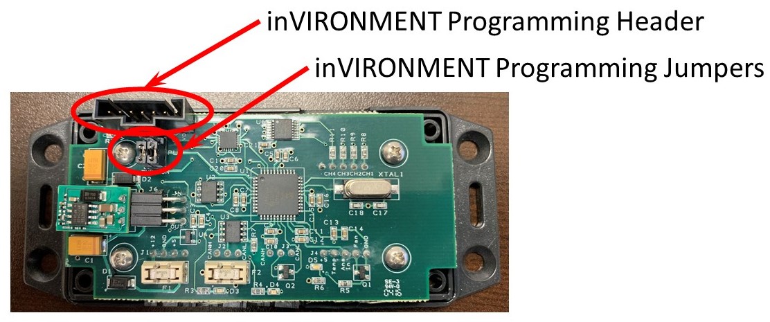
- Identify the Programming Header Connector and the Programming Jumpers. This picture will show you where they are on the inVIRONMENT board.
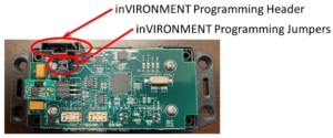
Picture of the Infinitybox inVIRONMENT Board Showing the Programming Header and Programming Jumpers
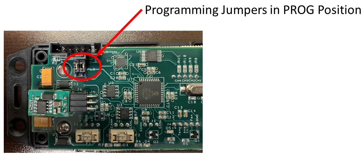
- Move the two Programming Jumpers from the RUN position to the PROG position. The PROG position puts the two jumpers on the pins closest to the Programming Header. You can use a pair of needle-nose pliers or a pair of tweezers to remove these jumpers and move them to the PROG position. FAILURE TO DO THIS STEP WILL DAMAGE THE inVIRONMENT PROCESSOR AND WILL VOID THE WARRANTY. This picture will show you the jumpers in the PROG position.
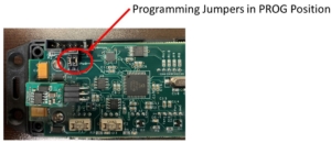
Picture of the Infinitybox inVIRONMENT Board Showing the Board Set for Programming
- Plug the inCODE connector into the Programming Header on the inVIRONMENT board.
- Launch the inCODE Program PIC software.
- Click on the BROWSE button in the Program PIC software and select the HEX file that we emailed to you. See the following picture for details.
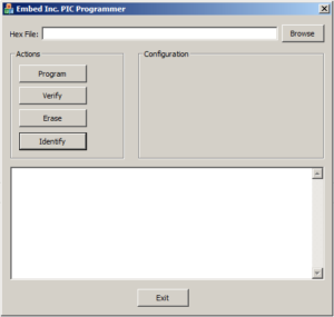
Picture of the inCODE Graphical User Interface
- Click on the PROGRAM button.
- Wait for the green light on the inCODE programmer to stop blinking. The last line of text in the Program PIC window should read “No Errors”.
- Unplug the inCODE connector from the Programming Header on the inVIRONMENT board.
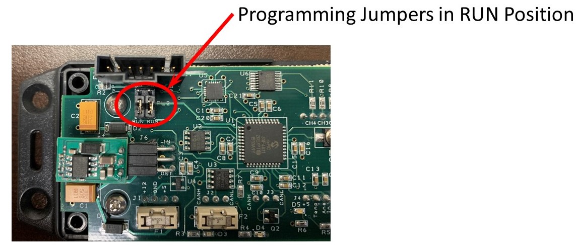
- Move the Programming Jumpers back to the RUN position. The RUN position puts the two jumpers on the pins furthest from the Programming Header. This picture will show you the correct position.

Picture of the Infinitybox inVIRONMENT Board Showing the Board Set for Run
- Replace the cover on the inVIRONMENT module and replace the 4 screws on the back.
- Reinstall the inVIRONMENT module in the car and plug in all of the connectors.
- Reconnect the battery.

If you have any questions about this process, please click on this link to contact our technical support team.
 Copyright Infinitybox, LLC 2021. All Rights Reserved.
 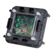 Copyright Infinitybox, LLC 2021. All Rights Reserved.