Wiring Turn Signals- Limeworks TS1342
We get a lot of questions about wiring turn signals. Our MASTERCELL inputs are very flexible. These let you connect practically any switch to the Infinitybox system. We have other blog posts that show you how to wire GM-style steering columns to the Infinitybox MASTERCELL. You can check that out here. Flaming River columns and IDIDIT columns use the exact same connector so you can use the same instructions.
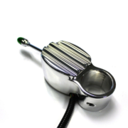
We got a call from a customer installing a TS1342 turn signal switch sold by Limeworks. This is a very classy turn signal switch with a very retro look. There are two versions: one for a 1 1/2″ column and one for a 1 3/4″ column. It also has a lit end that can be used as a turn signal indicator if you don’t have one on your dash.
The customer asked about how to wire the turn signal switch into his Infinitybox MASTERCELL. It’s is such a good question, we created a new application note for it and posted it.
The wiring diagram that comes with the switch shows the need to use a 3-prong flasher module. You need this if you’re connecting it to a traditional wiring harness. If you’re connecting it to our Infinitybox system, you don’t need the flasher. We build that into the system so no external flashers are required. This diagram shows you how to connect the Limeworks TS1342 turn signal switch into the Infinitybox system.
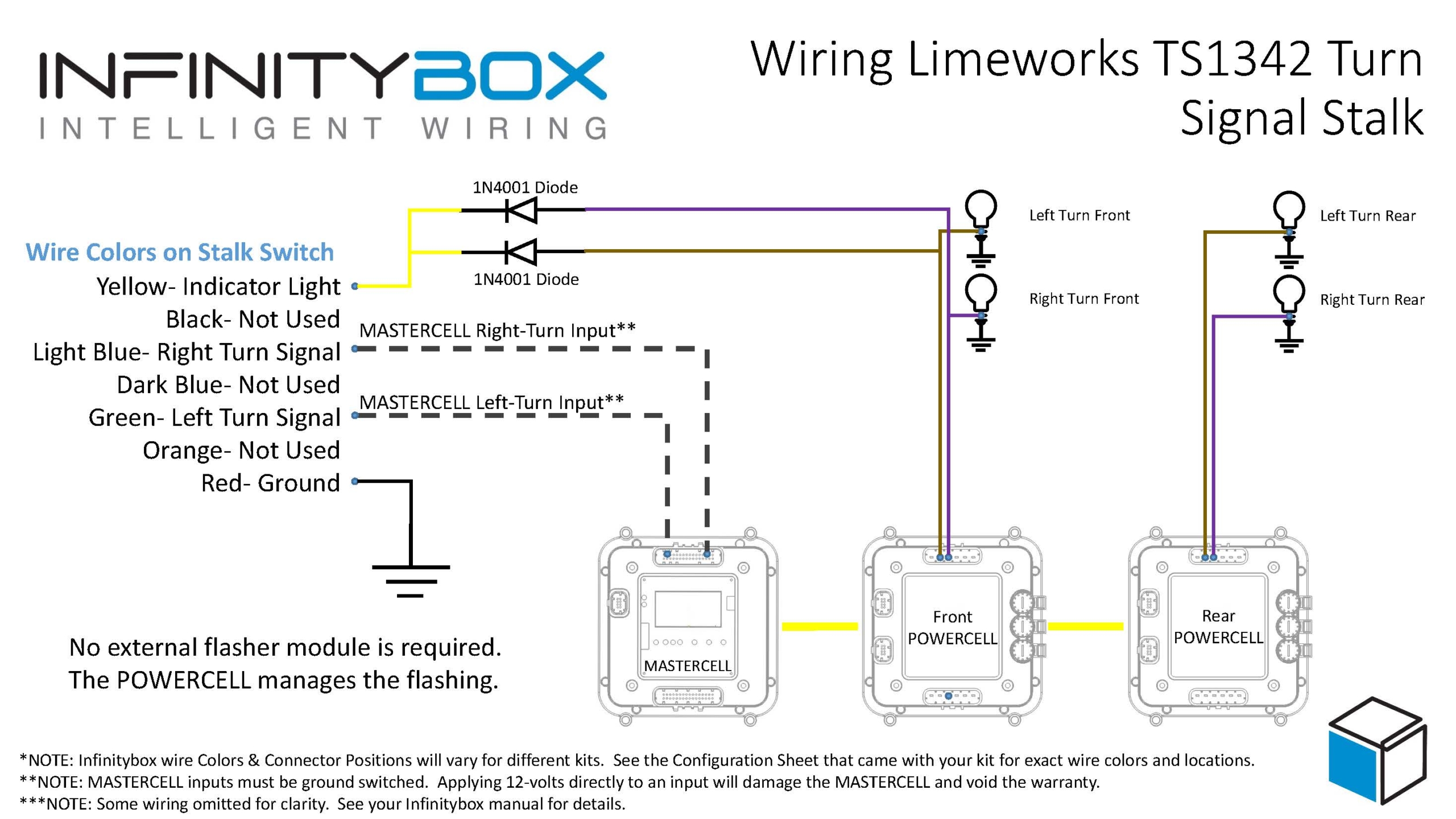
Picture of wiring diagram showing how to wire the Limeworks TS1342 turn signal switch with the Infinitybox system.
The MASTERCELL inputs work by getting connected to ground. This column switch was designed to supply battery voltage to a flasher, which fed the turn signal bulbs. As we said above, we can eliminate the flasher. To make it work with the MASTERCELL inputs, you simply ground the wire on the switch that was connected to the battery. The two wires that connected to the left and right turn signals will connect to their respective inputs on the MASTERCELL. That’s it. When you push the switch to the left, you’re electrically connecting the former power wire to the left turn signal input. Since the former power wire is grounded, the left turn signal input wire gets connected to ground. The MASTERCELL sees this and tells the POWERCELLs to flash the left turn signal. The same thing happens for the right turn signal. The diagram shows you which wires on the switch need to connect to the MASTERCELL inputs. Use the configuration sheet that came with your kit as a guide to identify the MASTERCELL wire colors.
The other thing that you’ll notice in our wiring diagram is that the brake pedal switch doesn’t get connected to the turn signal switch. The original wiring diagram had that because the brake pedal jumpered the left and right turn signals together for the brake lights. This is something that we manage within the MASTERCELL. If your rear turn signals are also your brake lights, you simply use the MASTERCELL input that is assigned to the 1-filament brake lights and connect that to your brake pedal switch.
The last thing to talk about in this post is turn signal indicators. Depending on your gauges, you can handle this a few different ways. If you have turn signal indicators on your dash, we recommend splicing off the left and right turn signal outputs on the front POWERCELL and connect them to the indicators. Most turn signal indicators draw very little current so you can run a light gauge wire, like 22-AWG from the POWERCELL outputs to the indicators. If you’re using LED’s make sure that you’re paying attention to their polarity. Also, check the voltage rating of your LED’s. Most are rated to 5 volts or less. You may have to add a resistor in series to limit the current flowing through the LED. Give our tech guys a call if you have question here.
One of the cool things about the TS1342 is that it has an indicator light on the tip of the stalk. It can flash when the turn signals are flashing. To do this, you need to splice off the POWERCELL outputs for the left & right turn signals like I mentioned above. Since there is only one light, you need to connect the outputs together. However, you need to put diodes in the circuit to isolate the left turn signal from the right. Without these diodes, the left turn signal would flash when the right was flashing and vice veat companies like www.digikey.com or www.mouser.com. Or you can pick these up at a Radio Shack if they are still open where you are. See the diagram for details on how to install these diodes. Remember, the orientation of the diodes is critical.
You can download a PDF of this application note showing wiring turn signals using the Limeworks TS1342 turn signal switch. If you have any questions about this, feel free to reach out to our technical support team at (847) 232-1991. Or click on this link to contact our team directly.
 Copyright Infinitybox, LLC 2021. All Rights Reserved.