Posts

Updating inTOUCH MAX Screen

This blog post will walk you through the steps to update the screens and code on an Infinitybox inTOUCH MAX Screen.

Please note that these instructions are for the legacy inTOUCH MAX screens that were manufactured through 2013.  If you have an inTOUCH NET smart device interface, this does not relate to you.  Unless specifically directed by a technical support representative from Infinitybox, you do not need to do this.  You can stop reading here.  

Here are the instructions.

  1. You will need an SD card that is a maximum size of 2GB (a smaller card will work fine).  It must be formatted as FAT16 (or just FAT) not FAT32 on a PC not a Mac.  You can find a video showing how to do this by clicking this link.
  2. You will receive an email from Infinitybox technical support that will have the files needed to be loaded onto the SD card.  Save these files to the SD card.  Do not put these in a folder on the SD card.
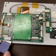
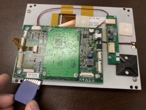
  3. Power down the touch screen and the complete Infinitybox system.  Insert the SD card into the slot on the screen. The SD card slot is located on the opposite side of the circuit board where the REACH serial number sticker is.  This picture will show you where the SD card slot is and the proper orientation of the card.

    Location of the SD Card Slot on the Infinitybox inTOUCH MAX Screen

    Location of the SD Card Slot on the Infinitybox inTOUCH MAX Screen

  4. Power up the system, the screen should be blank and the green LED labeled D1 on the back of the screen should be lit and the LED labeled D2 should be flashing rapidly. After about 30 seconds, the D2 LED will stop flashing and the screen back light will turn on.
  5. The screen is now reprogrammed, remove power from the screen and remove the SD card.

Please contact Infinitybox technical support with additional questions.

Updating inVIRONMENT

This blog post will cover the steps to update the software on our inVIRONMENT Vintage Air Gen-IV Interface Controller.

Before you get too far, 99.99% of our customers will never need to update inVIRONMENT in the field.  This blog post is intended to have this documented for the 0.01% of them that will.  The only reason why you’d need to update inVIRONMENT would be if you are converting a legacy system to a newer version.  In the overwhelming majority of cases, you can stop reading here.  You need to do nothing with the code on your inVIRONMENT unless explicitly directed by one of our technical support engineers.  

You also would not be updating inVIRONMENT without updating the MASTERCELL and other cells in your system.  This blog post is going to assume that you have already installed the software to run the inCODE programmer and you have followed the steps to set that up.

NOTE: DO NOT PLUG THE inCODE CONNECTOR INTO THE inVIRONMENT PROGRAMMING HEADER UNTIL AFTER YOU HAVE SET THE PROGRAMMING JUMPERS IN STEP 6.  DOING DO WILL DAMAGE THE inVIRONMENT PROCESSOR AND WILL VOID THE WARRANTY.  

Here are the steps.

  1. Save the inVIRONMENT HEX file to the desktop of your computer.  This would be in the email sent to you from Infinitybox technical support.
  2. Disconnect the battery.
  3. Remove all connectors from the inVIRONMENT module and take inVIRONMENT out of the car.
  4. Remove the 4 screws from the back of inVIRONMENT and take off the cover.
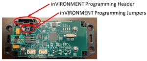
  5. Identify the Programming Header Connector and the Programming Jumpers.  This picture will show you where they are on the inVIRONMENT board.

    Picture of the Infinitybox inVIRONMENT Board Showing the Programming Header and Programming Jumpers

    Picture of the Infinitybox inVIRONMENT Board Showing the Programming Header and Programming Jumpers

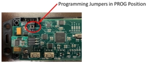
  6. Move the two Programming Jumpers from the RUN position to the PROG position.  The PROG position puts the two jumpers on the pins closest to the Programming Header.  You can use a pair of needle-nose pliers or a pair of tweezers to remove these jumpers and move them to the PROG position.  FAILURE TO DO THIS STEP WILL DAMAGE THE inVIRONMENT PROCESSOR AND WILL VOID THE WARRANTY.  This picture will show you the jumpers in the PROG position.

    Picture of the Infinitybox inVIRONMENT Board Showing the Board Set for Programming

    Picture of the Infinitybox inVIRONMENT Board Showing the Board Set for Programming

  7. Plug the inCODE connector into the Programming Header on the inVIRONMENT board.
  8. Launch the inCODE Program PIC software.
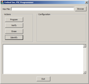
  9. Click on the BROWSE button in the Program PIC software and select the HEX file that we emailed to you.  See the following picture for details.

    Picture of the inCODE Graphical User Interface

    Picture of the inCODE Graphical User Interface

  10. Click on the PROGRAM button.
  11. Wait for the green light on the inCODE programmer to stop blinking.  The last line of text in the Program PIC window should read “No Errors”.
  12. Unplug the inCODE connector from the Programming Header on the inVIRONMENT board.
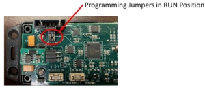
  13. Move the Programming Jumpers back to the RUN position.  The RUN position puts the two jumpers on the pins furthest from the Programming Header.  This picture will show you the correct position.

    Picture of the Infinitybox inVIRONMENT Board Showing the Board Set for Run

    Picture of the Infinitybox inVIRONMENT Board Showing the Board Set for Run

  14. Replace the cover on the inVIRONMENT module and replace the 4 screws on the back.
  15. Reinstall the inVIRONMENT module in the car and plug in all of the connectors.
  16. Reconnect the battery.

If you have any questions about this process, please click on this link to contact our technical support team.

Updating inMOTION

One of the advantages of our Infinitybox system is that it can always be updated.  We have added a lot of new features and functions over the years.  The earliest systems that we sold can be updated to use these new features.  In some cases, these updates require a simple hardware change that we need to do here.  In the majority of these changes, it is a simple software update that can be done in your shop, garage or in the vehicle in the field.  Most of the changes are done to the MASTERCELL but in some cases, the POWERCELLs and inMOTION cells need to be updated.  This post is going to talk about updating inMOTION.

Before you get too far, 99.99% of our customers will never need to update inMOTION in the field.  This blog post is intended to have this documented for the 0.01% of them that will.  The only reason why you’d need to update inMOTION would be if we have created something custom for you in terms of the current levels for the express functions.  In the overwhelming majority of cases, you can stop reading here.  You need to do nothing with the code on your inMOTION unless explicitly directed by one of our technical support engineers.  

inMOTION is different from a POWERCELL in a few ways.  inMOTION uses special polarity reversing relays instead of MOSFETs.  Also, inMOTION monitors the current flowing to the loads that it is powering.  inMOTION is always comparing the actual current to a learned value.  If the actual current exceeds the learned value, it shuts the output off.  One of the last steps of setting up inMOTION is to train it.  This is detailed in the instruction manual for inMOTION.  When you update inMOTION, there are a few extra steps that you need to follow because of the current monitoring and the way inMOTION learns its current draw.

Our technical support team will let you know what cells in your system will need to be updated if we are changing the way your system operates.  If you are told to update inMOTION, we will email you a new file.  Please follow these steps when updating inMOTION.

  1. Power down the entire system.
  2. Disconnect CAN cable and output harnesses from the inMOTION cell (just leave the power connectors)
  3. Unlike the other cells, the inMOTION cell needs power to program it, so power up the 12V feed to the cell.
  4. Connect the programmer to the inMOTION cell and browse for the inMOTION file
  5. Click program and wait for programmer to finish.
  6. Once the programming is complete, remove the programmer and the blue LED on the inMOTION cell should be blinking quickly.  Stop here if the Blue LED is not flashing quickly.
  7. Remove power from the system and re-connect the CAN cable to the inMOTION (do not reconnect any motor loads yet)
  8. Power up the entire system, wait about 10 seconds
  9. Press and hold the train button (S11) on the inMOTION cell until the blue LED is on steady and then release.  This process nulls out the current sensors in the system.
  10. Wait for the inMOTION to cycle all of the relays.
  11. Leaving the power on, reconnect the motor loads to the cell.  The blue LED should be doing a double flash heartbeat.
  12. Position the motors to the middle of their travel using the manual buttons on the inMOTION cell.
  13. Press and hold the train button (S11) until the blue LED is on steady and then release.  The inMOTION will cycle all of the motors and learn the current profiles.
  14. The blue LED should have the regular heartbeat now and everything should be ready to go.

Click on this link to contact our technical support team with any questions about updating inMOTION.

Personalities- Programmable Wiring Harness

The Infinitybox system has many powerful features that you just can’t get from a traditional fuse and relay harness.  One of the most powerful are what we call Personalities. These tools will help you to get the most out of the wiring harness for your car, truck or specialty vehicle.  Our Personalities give you a completely programmable wiring harness system.

A Infinitybox Personality describes how an output turns on when you turn on a switch.  It is something that we manage in the software of the system and it gives you great flexibility for the functions of your electrical system.  You connect your switches to the input wires on the MASTERCELL.  When you turn on a switch, the MASTERCELL sends a command to the POWERCELL.  This command tells the POWERCELL to turn on an output.  In this command it also tells the POWERCELL how to turn on the output and how it should work.  This is what we call a Personality.

Our most basic personality is what we call TRACK.  This means that the output TRACKs the switch on the input.  When the switch is on, the output is on.  When the switch is off, the output is off.  This is pretty simple.  Most of the outputs in your Infinitybox system will use the TRACK personality.  Headlights are a great example of the TRACK personality.  When you turn on the headlight switch, the headlight output on the front POWERCELL will turn on.  When you turn off the switch, the headlights turn off.  Brake lights are another example.  The brake lights will TRACK your foot pressing the brake pedal.  When your foot is on the pedal and the switch is closed, the brake lights on the rear POWERCELL are on.  When you lift your foot and the switch opens, the brake lights turn off.  Other examples of use of the TRACK personality include ignition, starter, running lights, fuel pump and horn.

Another great personality is TOGGLE.  When we use the TOGGLE personality, a momentary input to the MASTERCELL will command a POWERCELL output to turn on.  Another momentary input to the same wire on the MASTERCELL will send a command to turn the same POWERCELL output off.  In most cases, you’re using a momentary push-button connected to the MASTERCELL input.  When you press and release this button, the MASTERCELL will command the POWERCELL to turn on an output.  Pressing and releasing the button again, the MASTERCELL will command the POWERCELL to turn the output off.  A lot of our customers use TOGGLE when they are putting simple momentary buttons on their dash to replace the OEM switches.  You can use TOGGLE for things like headlights, running lights and parking lights.

A variant of the TOGGLE personality is our 1-BUTTON START.  This replicates most modern OEM single button starting systems.  If you use a traditional ignition switch to turn on your ignition and start your engine, there are separate inputs for the ignition and starter.  Both of these inputs use the TRACK Personality.  The ignition is on as long as the switch is on.  In all of our kits, you have the option to use a different MASTERCELL input wire and connect it to a momentary button.  This will get you our 1-BUTTON START function.  When you press and hold the button, the MASTERCELL turns on the ignition output, waits 1 second for the fuel pump to prime, they cranks the starter.  Once the engine starts, you release the button.  The MASTERCELL will turn off the starter output but will leave the ignition output on so that the engine will run.  To stop the engine, you simply press and release the button again.

We also have several personalities built into the system to manage turn-signals and 4-way flashers.  With the Infinitybox system, you do not need any external flashers.  The POWERCELL flashes the outputs automatically, even if their LED’s.  This link will take you to more information on the personalities used for turn signals and 4-way flashers.

Another common personality is TIMED.  This lets you time outputs on your POWERCELL.  Instead of having to add external timers, we build this into the system.  Examples include headlight timers.  When you turn off your car, you headlights can stay on for 30 seconds while you get out of your garage.  Or you can time your cooling fan to continue to run after you turn off the ignition.  These are very easy things to do in the Infinitybox system.  With a traditional wiring harness, you’d have to add additional modules to make this work.

Here’s one last personality example for this blog post.  We use MOSFETs in our POWERCELLs instead of relays.  This lets us do some things that no other system can do.  One of the coolest is THEATRE DIMMING.  This replicates what all new cars do.  We can set your interior lights to gradually fade when you close your door.  This is built into the system and requires no additional hardware.  When you close your doors, we pulse the POWERCELL output to your dome lights to make it fade gradually.  It is a simple and elegant effect that makes your classic car feel like the latest OEM car.

When you get a 10 or 20-Circuit Harness kit from Infinitybox, you get a configuration sheet that is specific to your wiring system.  It lists all of the personalities for each of the outputs in your harness.  This link will take you to the configuration sheet for our most popular front-engine configuration.

There are many more examples of Personalities that can be applied to your Infinitybox system.  Give our technical support team a call at (847) 232-1991 to talk through how we can tailor a wiring system specifically to your project.  You can also click on this link to contact our team directly.  

Updating with inCODE

Updating with inCODE is very simple but there are two very important warnings that you must understand before you go any further.

***DO NOT PLUG THE inCODE PROGRAMMER INTO YOUR COMPUTER UNTIL YOU HAVE INSTALLED THE SOFTWARE PER THE INSTRUCTIONS BELOW***

…and…

***PAY ATTENTION TO WHICH CELLS YOU ARE UPDATING.  IF YOU RECEIVED A FILE TO UPDATE YOUR MASTERCELL, ONLY LOAD THAT ON A MASTERCELL.  IF YOU RECEIVED A FILE FOR YOUR POWERCELLS, ONLY LOAD THAT CODE ON YOUR POWERCELL.***

That being said, let’s take a look at the steps for updating with inCODE.

One of the advantages of our Infinitybox system is the ability to load new configurations to it in the field.  This video goes through the process of updating your Infinitybox MASTERCELL.

***DO NOT PLUG THE inCODE PROGRAMMER INTO YOUR COMPUTER UNTIL YOU HAVE INSTALLED THE SOFTWARE PER THE INSTRUCTIONS BELOW***

Here are the instructions to load the software and update your system using the inCODE programmer.  This will work for any Windows operating system running at 32-bits or 64-bits.  Please note that there is no application that will work for Apple or Mac.  Also, this must be done from a PC or a laptop.  You cannot use a tablet to run inCODE.  Contact Infinitybox technical support to get a link to download the software to run the inCODE.  You can contact our team by clicking this link.

  1. Temporarily disable your virus scanning software.
  2. Download the software application from the link provided to you from Infinitybox technical support.
  3. Run the install_picprg executable.
  4. When the installation is done, plug the programmer into the computer.  Let it find the drivers as necessary.
  5. Reboot the computer.
  6. Go to Programs/Embed Inc/Program PIC.
  7. Save your hex file to your desk top.
  8. UNPLUG ALL CONNECTORS FROM THE CELL BEFORE YOU PLUG THE inCODE PROGRAMMER INTO IT.
  9. Plug the programmer header into the cell to be updated.  Follow the instructions that came from Infinitybox technical support carefully.  Loading code on the wrong type of cell can cause severe damage to the system.  For example, programming a POWERCELL with MASTERCELL code will cause damage to the cell.
  10. Browse for the file and hit PROGRAM on the GUI.

The programming window looks like this:

Picture of the inCODE Graphical User Interface

Picture of the inCODE Graphical User Interface

When completed, unplug the inCODE programmer from the cell and plug the harness connectors back in.

PLEASE NOTE:  You may get a warning from your anti-virus software about the inCODE download.  It depends on the browser and the anti-virus software that you are using.  We test this software frequently and know that it is safe.  Contact our technical support team with questions about this.

If you plug the inCODE programmer into your computer before you install its software, Windows will randomly assign a driver to it.  The inCODE programmer will not work correctly when you install the software.  To fix this, please follow these instructions by clicking this link.

Please contact our technical support team by clicking this link if you have questions.