Central Locking
We created our inMOTION cell about 6 years ago to handle things that need to change direction. From any MASTERCELL input, you can control power windows, lock actuators, exhaust cut-outs and other linear actuators. What makes inMOTION unique is the fact that it changes polarity from within the cell. This means that you don’t need special relays to change the polarity of the current flowing to your window motors or lock actuators. inMOTION does that for you. You can also control any of the inMOTION outputs from our inLINK key fobs and any smart device through inTOUCH NET. This post is going to show you how to wire lock actuators with Central Locking to the MASTERCELL and inMOTION cell.
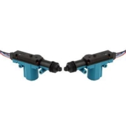
There are lots of ways to control door lock actuators. In most cases, our customers want to unlock their doors when they disable security from their inLINK key fobs. That’s easy. From the inside of the car, they usually want switches that lock and unlock the doors. That’s easy. Another way to handle this is to use the central locking feature built into the MES 5-Wire Door Lock Actuator. Our good friends at Electric-Life sell these. You can see them at this link.
These lock actuators do two things. First, they lock and unlock the doors. That’s pretty basic. They also have switches built into them to control central locking. When you pull up on the door lock knob, it pulls on the lock actuator mechanism and closes a switch internally. This switch sends a signal to the Infinitybox MASTERCELL to pulse the lock output on inMOTION to unlock the rest of the doors. Pushing down on this same door lock knob closes another switch inside the actuator that closes a second switch. This second switch is connected to another MASTERCELL input that sends a signal to inMOTION to lock the doors. Take a look at this wiring diagram.

Image of Infinitybox wiring diagram showing how to wire 5-wire lock actuators
There are a few things to consider when using these lock actuators.
- Check the wiring diagrams that come with the actuators to confirm the wire colors in our drawing.
- Depending on how you have the actuators oriented in the car, you may have to change the wiring for the inMOTION outputs and the central locking switches. You want the up and down directions to be the same on all actuators and you want the lock switches all in the same direction. Check to make sure everything is working correctly before you finalize you wiring connections.
- You must properly adjust the linkage for the lock mechanism so that you can get full range on the actuator plungers when you pull up and push down on the lock knob.
- Make sure that you train the inMOTION cell correctly. Follow the instructions that came with your inMOTION kit.
You can download a PDF of this wiring diagram by clicking this link.