 Copyright Infinitybox, LLC 2021. All Rights Reserved.
 MS3Pro EVO ECU
Here’s another post showing you how to connect your Infinitybox wiring system to a popular EFI system. We had a customer ask about wiring the MS3Pro EVO ECU with our Infinitybox 20-Circuit Kit. This is a very powerful engine management system that can be easily connected to Infinitybox.
MS3Pro ECU
Just like any other ECU, you must thoroughly read and understand the manual that comes with the hardware. AMP/EFI has a very comprehensive manual that covers all of the details of this ECU. You can download that by clicking this link. The other important thing to note about this blog post is that we are only showing how to connect the Infinitybox system to the MS3Pro EVO ECO. This includes the wiring for ignition power, the cooling fan trigger and the fuel pump trigger. Consult their manual for the rest of the engine wiring.
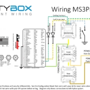
This picture shows the details of wiring the ignition power from your POWERCELL and the MASTERCELL inputs for the cooling fan and fuel pump.

Picture of wiring diagram for MS3Pro EFI system and the Infinitybox system.
There are multiple grounds in the MS3Pro EVO ECU harness. You must have a solid, metal-to-metal connection to ground for all of these wires.
From there, the ECU needs key on power from the ignition. Consult the configuration sheet that came with your system for the proper POWERCELL output wire for your ignition. That will connect to terminal 25 on the White Connector on their ECU. See their documentation for more details.
The ECU is set up to ground switch a relay for the fuel pump. You can connect your fuel pump input to the MASTERCELL to this pin on their ECU. You must install a blocking diode to isolate the MASTERCELL from the ECU. See our wiring diagram for the wire details and for the orientation of the diode. Improper installation of this diode will make this inoperable.
You can also program the MS3Pro EVO ECU outputs to control the fuel pump. These outputs are ground switched so they can be wired in a similar way to to the fuel pump. Just like the fuel pump, you must install a blocking diode between the ECU and the MASTERCELL. See our wiring diagram for wire details and diode orientation.
For both the cooling fan and the fuel pump, you must not program the ECU to pulse-width modulate these outputs. They must either be on or off.
You can download a copy of this wiring diagram by clicking on this link.
Please click this link to contact our technical support team with questions.