Making Turn Signal Noise
We spend a lot of time educating customers on what a MOSFET is and why it is better than a mechanical relay. All of the outputs on our POWERCELLs are controlled by MOSFETs. They are more efficient than relays, they generate less heat, the have no moving parts, they never wear, we can PWM outputs, etc. The lists of benefits can go on for hours. One of the biggest advantages of a MOSFET can also be a disadvantage. Since it has no moving parts, it makes no noise when it turns on and off. In the case of turn signals, that can be a disadvantage.
In a traditional wiring system, electro-mechanical flasher modules are used to flash the turn signals. These are typically bi-metal devices that have been around since the dawn of the automotive industry. When you turn on your flashers, current flows through a element in the flasher module. This heats up a special combination of metals laminated together. After a short period of time, this element flexes and separates a contact. When it separates, the current stops flowing and the element cools down. This lets the element snap back to its starting position which makes the connection again. The element heats up and the cycle repeats over and over until your turn your signals off. The mechanical movement of this element in the flasher module is what makes the clicking sound.
This video shows how it works. Thanks to Chris at Mustang Restorations in Dundee, Illinois for creating this.
You may have noticed in most new cars that the turn signals sound different from most classic cars. All new cars are using multiplexing technology similar to our Infinitybox system. This means that they are replacing the traditional flasher module with MOSFET control. They have tone generators behind the dash that create a synthetic turn signal sound.
Just a quick note about the video above. If you carefully watch the contacts in the flasher module after Chris removes the cover, you will can see arcing (little sparks) between the contacts as the flasher cycles on and off. This arcing gradually erodes the contacts in the flasher and causes them to fail over time. Since our POWERCELL outputs use solid-state MOSFETs, there are no moving contacts to arc and erode over time. You can flash your turn signals billions of times with no change in their performance.
We occasionally get questions from customers asking how to create a clicking sound when their turn signals are on. We’ve blogged before about how to wire the turn signal indicator lights on your dash. This wiring diagram will show you how to get a clicking sound with your turn signals.
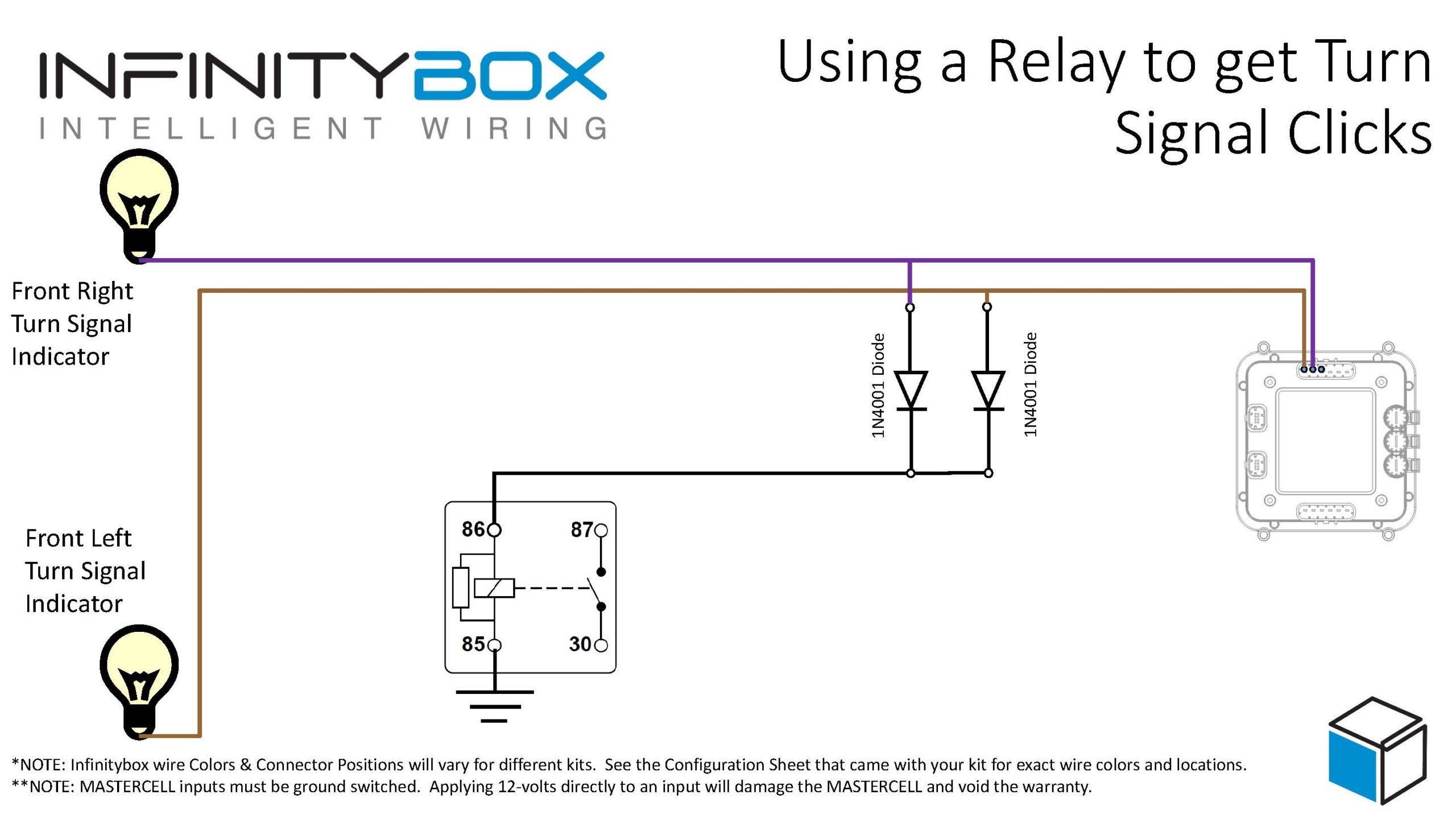
Image of wiring diagram showing how to wire the Infinitybox system to get sounds with your turn signals
You are going to add a relay behind your dash. This isn’t going to carry any current, you’re just going to use the mechanical action of the relay to make a clicking sound. You simply tap off of your POWERCELL outputs for your left and right turn signals. These get wired to the coil of a relay through two diodes. These diodes are very important because they isolate the two turn signal outputs from each other. Without these diodes, both of your turn signals would be connected electrically and would turn on together. These diodes should be 1N4001. You can easily get them from Amazon. The orientation of these diodes is critical. Please note the position of the cathode in the wiring diagram. This will not work if they are not oriented correctly.
For all standard relays, the coil terminals are 85 and 86. Connect your turn signal outputs through the diodes to terminal 86, then ground terminal 85 to the chassis.
We recommend a relay like this one.
Example of an automotive 12-volt SPDT Relay
You can purchase this relay and its terminals at Waytek Wire. This is a good relay to use because it has an integrated mounting tab. That makes it easy to mount behind your dash. It also will help sounds to travel from the relay contacts to resonate your dash. You want to mount this in a place behind your dash to get good sound transfer. You may have to experiment with different locations to get the loudest results.
Here’s how this works. When you flip on your turn signal, the POWERCELL flashes the turn signal outputs. Power from the outputs flows into the coil of this relay. This pulls in the relay contact and makes a click. When the POWERCELL flashes the turn signal off, power is taken away from the relay coil. The contacts snap back to their rest position and make another click. This relay isn’t carrying any power, it is just making noise.
You can down a PDF version of this wiring diagram by clicking this link.
Please let us know if you have any additional questions related to this post or anything else related to our Infinitybox wiring system. You can contact our technical support team with questions by clicking this link.