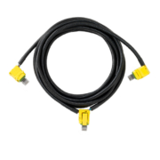
The CAN cable is the main backbone of the Infinitybox Multiplex System. It takes the commands from the MASTERCELL and routes them to the peripheral cells, like POWERCELLs and inMOTION cells, in a system. We get a lot of questions about this cable and how to work with it so we put this post together to answer these questions.
One of the first questions that we get is what does CAN mean? CAN stands for Controller Area Network. This is an automotive standard created to let different electronic systems talk together. It was originally developed by Bosch in 1983 so it’s been around for a while. You can read more about CAN at this link.
There area many different CAN protocols. When a company says they communicate on CAN, that is the equivalent of saying you speak English. English spoken in the Bronx sounds like someone speaking with a South-Side Chicago accent. Both use the same basic works but one may not completely understand the other because of inflections and local slang. The Infinitybox system uses a proprietary version of CAN 2.0b. We take this standard protocol and all extra data to get more functionality out of the system. We also have versions of our hardware that communicate on J1939, which is the commercial vehicle CAN standard.
Inside our CAN cable, there are two main wire: CAN High and CAN Low. These send the commands between the different cells in an Infinitybox system. Additionally, we run a power and ground wire to provide voltage to the MASTERCELL. The POWERCELLs have the ability to put out voltage through the CAN connector. There is a very important addendum that we include with our 20-Circuit Harness kits that talks about power and ground in the CAN cables. Please check out this link when you’re installing your kit.
A lot of guys ask where they can put their different cells on the 3-way cable that comes with the 20-Circuit Kit. On very long CAN cables, over 30 feet, you need to have the MASTERCELL on one of the cable and the POWERCELL with the terminator resistor on the other end. This has to do with proper impedance matching of the CAN High and CAN Low lines in the cable. For most aftermarket installs, where the CAN cable length is under 30 feet, you can put the MASTERCELL anywhere on the CAN cable.
A lot of guys also ask about the length of the CAN cable. We include a standard CAN cable length in the 10-Circuit and 20-Circuit Harness Kits. This length was derived from a few years of learning from our customers and how they place cells in their cars and trucks. We also have options when you order your kits to build custom CAN cable lengths. You can call our sales team about this. At the same time, there is nothing keeping you from extending or shortening your CAN cable in the system. You can do this a few ways.
The first option is to cut the cable and splice in a new length of wire or cut out a length of wire. There is nothing wrong with this and this is a completely acceptable way to do it. The wire that we use is 22-AWG TXL wire. You can buy this wire from a few sources. We get ours from Waytek Wire and you can buy it in reasonable lengths. This link will take you to the 22-AWG TXL section of their website. The colors that we use in our standard CAN cables are black, green, blue and red.
It is very important that you do not cross the wires in the CAN cable. When you’re reconnecting the connector, make sure that the wires go back where they came from.
If you’re going to splice the cables, we recommend a good butt splice connector and heat shrink. This link will take you to a good 22-AWG butt splice from Waytek. An 1/8″ piece of heat shrink over this will keep it protected and insulated. Here’s a link to heat shrink. The key to a good splice is a good crimp on the butt splice connector. The right tool will guarantee a good job and isn’t very expensive. Here’s a good tool for the crimp.
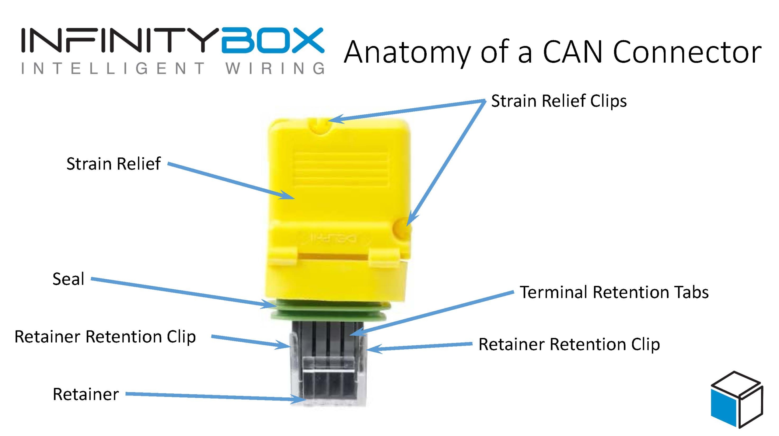
While a splice is completely acceptable, some guys don’t wan them in their wiring harness. We get that. You can create your own custom cable lengths and crimp the terminal right on the end of your wire to connect into the connector. The connector system used for our CAN cables is very easy to work with and requires no special tools. This picture shows you all of the parts that go into the CAN connector.

Imaging showing the different components of the Infinitybox CAN connector
The yellow part is called the strain relief. It helps to route the wires out of the connector. The green part is the seal. Please note that in some newer systems, the cable seals are black. It makes the connection between the connector and the mating port on the MASTERCELL or POWERCELL water tight. The grey part is called the connector. It holds the terminals from the harness. The last part is the retainer. This is the clear clip on the front end of the connector.
The terminals that are used in this harness are made by Aptiv. Their part number for the terminal is 15435885 and it can be sourced easily from Mouser. This link will take you there. This link will take you to a good quality crimp tool for these terminals.
You can cut your CAN cable to length and crimp the terminals onto the wires. These instructions will show you how to dissemble the connector to plug these terminals into the connector.
First, get a small screw driver and gently pry up on the strain relief clips on the strain relief. This part opens up like a clam shell. Next, remove the Retainer from the connector. Use a small screw driver or your fingernail to pry up on the short sides of the strain relief where it clips on to the grey connector. Once that is done, you can gently pry up on the terminal retention tabs on the grey connector. These hold the terminals into the connector. When you lift them, you can pull the wire with the terminal out through the strain relief.
Reassembly of the connector is just as easy. Crimp the terminals onto the wires and get ready to put it back together. Just make sure that you put the right wires back into the right cavities in the connector. The cavities area marked with an identification number on the inside of the strain relief. Here’s how the wires should go back in.
5- Black
6- Green
7- Blue
8- Red
Make sure that the terminals are pushed to the front edge of the grey connector. Once you have all of them in, you can snap the clear retainer back onto the grey connector. Then close the strain relief using the strain relief clips to hold it closed.
Give our team a call if you have additional questions about working with our CAN cable or the connector components. You can contact us directly by clicking this link.
 Copyright Infinitybox, LLC 2021. All Rights Reserved.