 Copyright Infinitybox, LLC 2021. All Rights Reserved.
 Power Input Cables
Here’s the next step in wiring the 1967 Mustang with our Infinitybox system. You need to run the power input cables from the Mega fuse holder and connect them to the POWERCELLs. There are 4 power input cables included in your kit. They look like this.
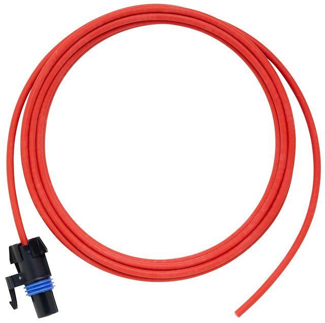
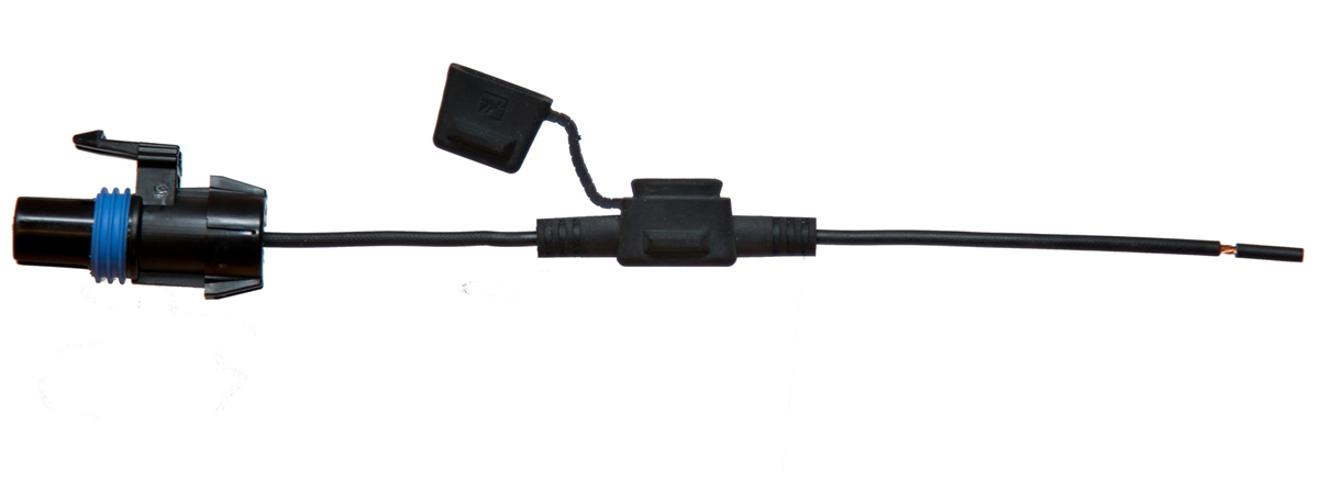
POWERCELL Battery Input Harness
These cables have the mating connector that plugs into the circular 8-mm sockets on the POWERCELL. These cables are 8-AWG and are jacketed in high-durability TXL insulation. Each POWERCELL gets two of these cables. This lets you supply a total of 120-Amps to the POWERCELL.
Remember how the POWERCELLs work. They are mounted locally in the car. Your functions like lights, fans, pumps, ignition and starter connect to the POWERCELL. The MASTERCELL sends commands to this POWERCELL through the CAN cable to turn these function on and off. In addition to the CAN cable that sends commands, the POWERCELL needs to get power from the battery for your switched functions. These primary input cables supply the power to the POWERCELL.
For this process, make sure that you have disconnected the positive cable from the battery. Plug the round connector on the end of each of the primary input cable into the POWERCELL and run the cable through the car. All three of the round connector ports on the POWERCELL are the same. You can pick any two of these to plug the cables into.
The other end of this cable needs to connect to the terminals on the Mega fuse holders installed earlier in this process. Cut the cable to length, strip it and crimp on the 8-AWG 5/16″ ring terminals that are included with your 10 or 20-Circuit kit. Make sure that you are using the right tool to make these crimps. Poor crimps cause many problems down the road. This link will take you to a simple tool sold by Del City that can be used for all of your primary power cables and battery cables.
We also strongly recommend covering the exposed area of the ring terminals with heat-shrink tubing. This will minimize exposed metal areas that can lead to short circuits in the car. Del City or Waytek are great sources for heat-shrink tubing.
If you need to, you can lengthen the primary power cables. You can use an 8-AWG crimped butt connector to splice in another length of cable or you can solder the strands together. Done correctly, either are a acceptable way to lengthen these cables.
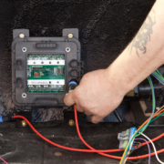
This picture shows plugging the primary power cables into the rear POWERCELL in our Mustang project.
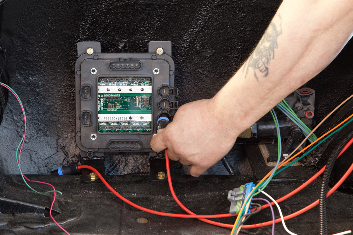
Plugging in POWERCELL battery input harness in Infinitybox system installed in 1967 Mustang
This picture shows the two primary power cables plugged into the front POWERCELL.
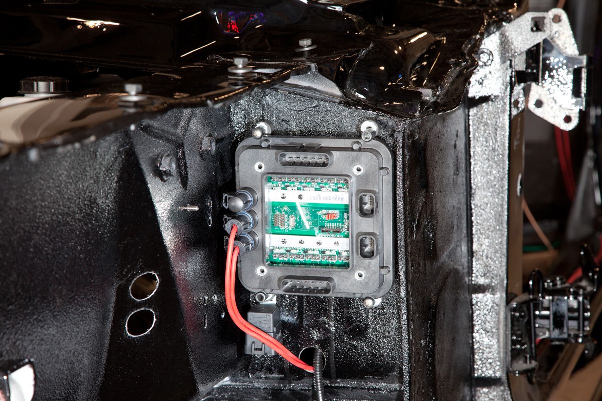
Front POWERCELL Mounted in 1967 Mustang
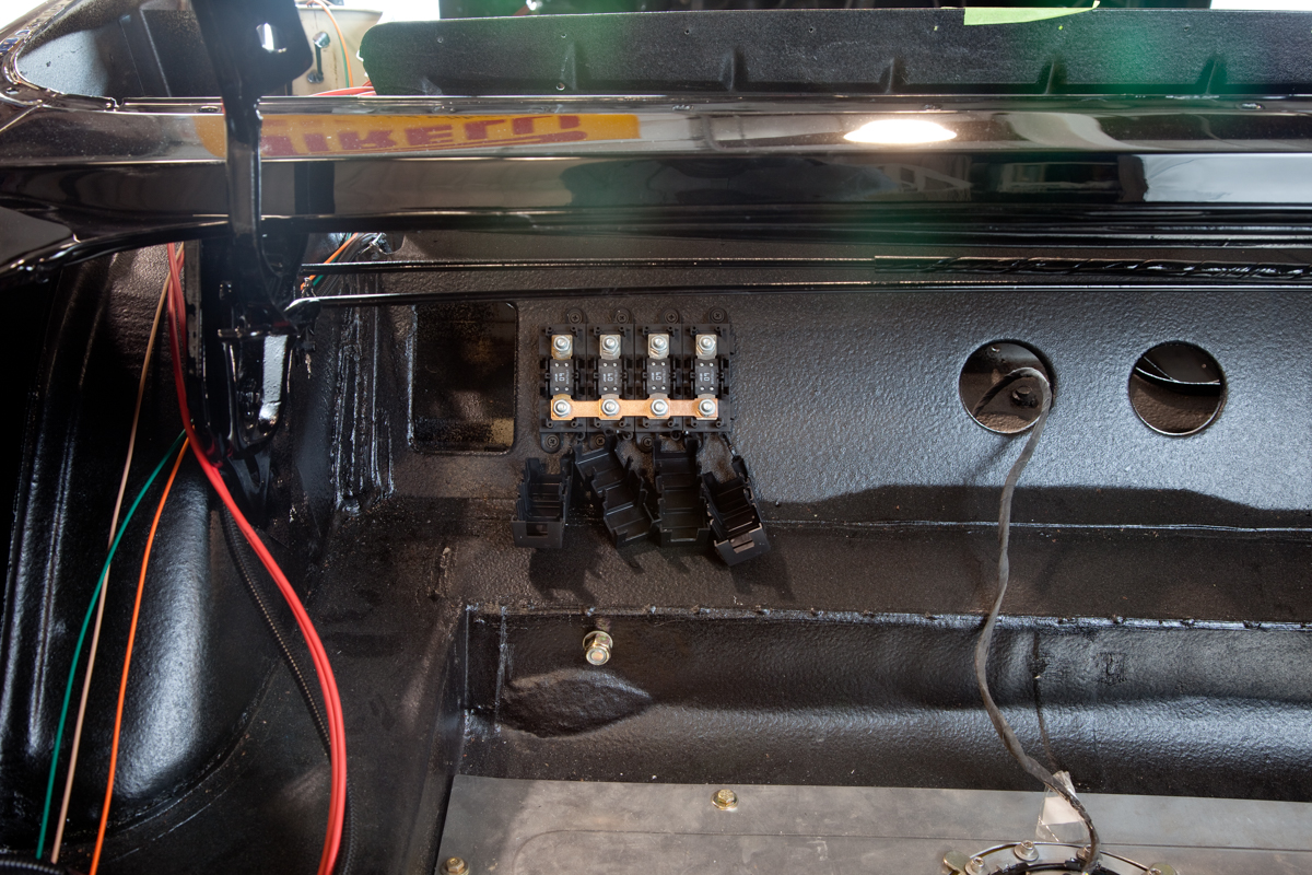
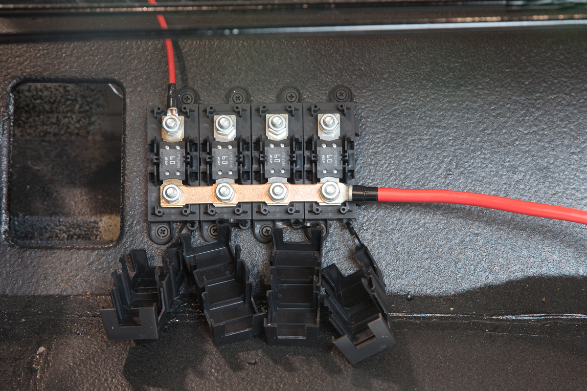
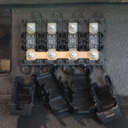
This picture shows the primary power cables connected to the Mega fuse holder block in near the battery in the rear of the car.
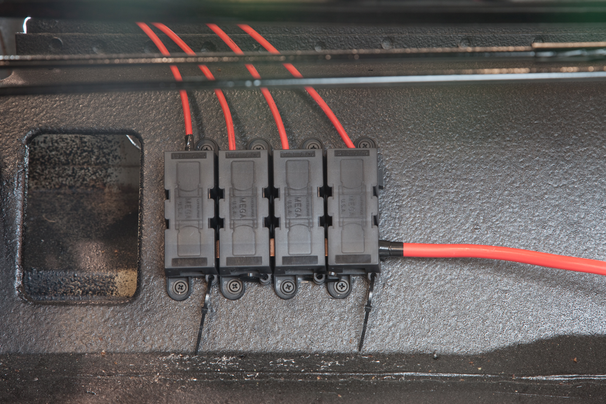
Assembled Mega Fuse block in 1967 Mustang wired with our Infinitybox system
Each POWERCELL has three power input ports on it. You are going to use two of these. To keep the cell sealed, you must plug the power input dummy plug into the unused port. This is included in your kit.
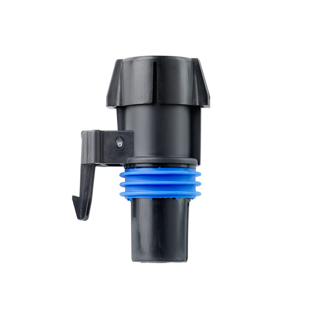
Sealing plug for POWERCELL battery input port.
You can also use one of our POWERPLUGs in the open port.
Power Plug
The POWERPLUG is a very easy way to get fused constant battery power from the POWERCELL. You can use this to power accessories like engine controllers, transmission controllers, audio and LED tail light controllers.
Now that you have the primary power cables properly connected to the primary fuses and the POWERCELLs, you can move on to the next step. Stay tuned for the next post. If you have questions in the meantime, you can contacts us by clicking this link.
 Copyright Infinitybox, LLC 2021. All Rights Reserved.